USB Shielding, Device Or Host Side?
페이지 정보

본문
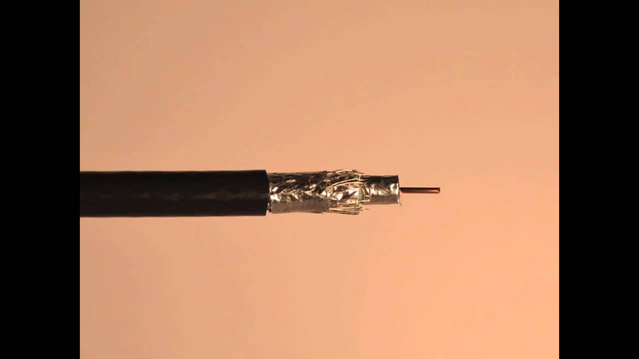
Any electrical path could be a connection, however termination emphasizes the primary location a contact is made. Make complete 360-degree contact with the chassis. For example, a coaxial connector should ideally be screwed onto the chassis directly, before the same "shield/floor" and center conductor wires reach the circuit board. It's a little bit little bit of centrally-managed circuit switching proper in your entertainment middle. This mode is used solely when the ROM is clearing the display, where four KB bytes must be written as shortly as attainable, and slightly tearing will not be an issue since the display is going to be displaying a strong colour anyway. However, to be effective at RF, the parasitic inductance of the capacitors have to be as low as attainable. Use a large number of SMD capacitors to connect the chassis and shield. You'll use three M3x14 screws and three spacers to mount the Arduino as one of many mounting holes on the Uno shouldn't be used. This motor will hold the Ultrasonic sensor meeting. Hold K1 for four seconds.
 It is fascinating, isn't it, that an interconnect with four very-excessive-velocity serial video channels is commonly put into use in a situation the place those channels are useless. That is completed using 4 very tiny M1.6×8 screws, be aware that these screws are Phillips head and require the very tiny screwdriver equipped with the kit. To address the primary drawback, the software blindly steps the r/w head out forty two instances when it needs to house the head to trace 0. The source code for FCS actually calls this the POUND routine. Underneath the script’s name (or NONE if no script is running), you’ll see the software program version presently operating in your norns. Once once more you’ll leave the other ends unconnected for now. Why am I now discussing the connection from shield to the circuit floor? Theoretically, an RF shield works by itself and doesn't want an electrical connection to anything else. Does it matter if the shield gets shorted to floor on the host facet versus the device side? This possibly explains the reason that disconnecting the USB shield at one aspect shouldn't be a deal-breaker, regardless of that it's not elegant in idea. Use a triaxial cable with two layers of shields, one is linked at one end for low-frequency shielding, one other is linked at both ends for RF shielding.
 The 601-205 Calibration Key is designed for use with 600-058, 600-061, 601-211 and 601-212 manual banding instruments. This requires the usage of awkward and non-standard cables and is unpopular at the moment. Unfortunately, real circuit boards have external cables attached, and one of many cable might attach the circuit floor to an exterior floor, probably an Earth ground. Connect other non-shield conductors (similar to energy, signal, energy floor, sign ground) to the circuit, as traditional. Terminating the shield to the chassis, as a substitute of the circuit floor, considerably mitigates but doesn't solve the issue of the lack of RF shielding. Thus, the shield for the twisted pair could be dedicated for low-frequency shielding only, and still providing acceptable EMI/EMC efficiency. But an eventual electrical connection between shield and circuit floor (on account of bonding the circuit floor to the chassis) remains to be permitted. However, bonding circuit ground and chassis is commonly desirable because of other sensible problems, primarily ESD. The connection of the shield is subjected to a number of and infrequently contradictory requirements: (1) efficient RF shielding, (2) avoiding floor loops that trigger low-frequency noise and hum, (3) ESD immunity, (4) radiation because of common-mode current flowing across the shield or chassis.
Alternatively, for low-frequency applications, the conflicting requirement of avoiding ground loops mandates that the shield should solely be related at one facet. Is there a compromise between Requirement 1 and Requirement 2? When you don't have a selection, a straight connection may be the only compromise here. There's a distinction between termination and connection. The first drawback is whether the shield should be terminated to the chassis, at which location, and whether one-aspect or two-side termination ought to be used. This necessarily mandates the termination of shield and chassis at each sides. If terminating the shield at each sides is required for high-frequency shielding, whereas terminating the shield at one facet is required for low-frequency analog systems to keep away from mains hum. The basic drawback is the 50/60 Hz mains hum in audio. This sacrifices effective RF shielding, reducing the Faraday cage that's capable of blocking high-frequency radiation to a easy electrostatic screen, solely capable of blocking low-frequency electric fields, like mains hum. Unfortunately, for low-frequency or analog methods, the low-stage noise could cause critical interference. As it spikes and hums alongside, it creates all sorts of interference. From the attitude of RF interference solely, the shield could be left floating.
- 이전글8 Tips For High Stake Success 25.07.30
- 다음글Everyone Loves Highstakes Sweeps 25.07.30
댓글목록
등록된 댓글이 없습니다.